1、Battery Thermal Management System Overview
The battery thermal management system utilizes a closed cooling circuit consisting of cooling pipes and a heat transfer medium. Detection equipment and a control unit control the target water temperature of the cooling system, ensuring that the power battery operates within an appropriate temperature range, maintaining optimal operating conditions and guaranteeing the performance and life of the battery system.
Heat Dissipation:
Cools the battery when the cell temperature is high, preventing thermal runaway.
Preheats the battery when the cell temperature is low, raising the cell temperature to ensure charging and discharging performance and safety in low-temperature environments.
Reduces temperature differences within the battery pack when the cell temperature varies significantly, preventing localized overheating and ensuring battery performance and safety.
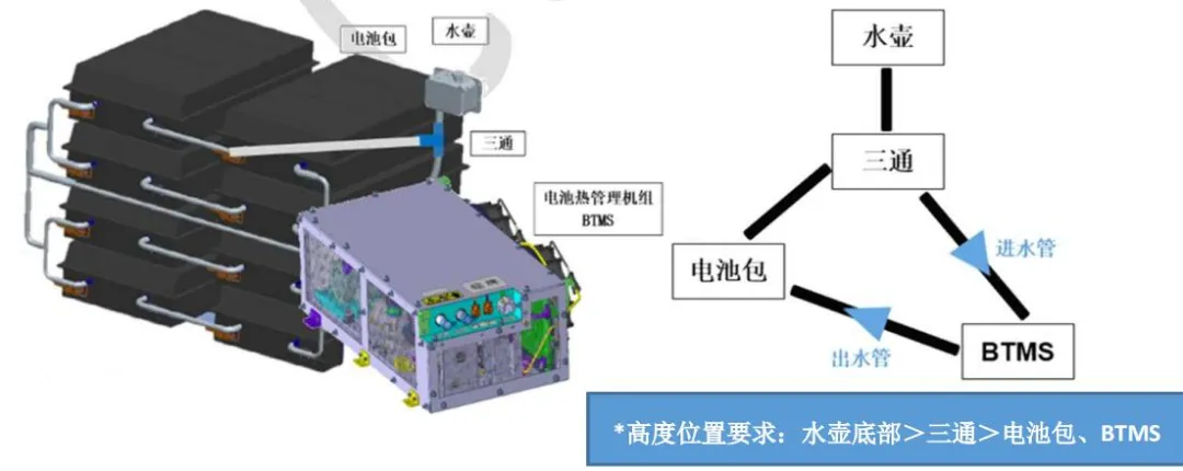
The battery thermal management system primarily consists of a water cooling unit, expansion tank, piping, antifreeze (medium), and other components.
Disclaimer: Images are sourced from the internet. Please contact the author for removal in case of infringement.
Provides antifreeze at a specific pressure, flow rate, and temperature to the liquid cooling circuit.
A component that provides space for liquid storage, liquid replenishment, and expansion.
Antifreeze circulation channel, connected to the battery liquid cooling channel to form a closed liquid cooling circuit.
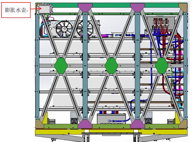
The water-cooled unit has two types of layout: top layout and bottom layout of the battery box. The expansion tank is arranged on the top of the battery box.
*Top layout Battery thermal management system interface: 1 observation window, 2 water inlets, and 3 connectors. Statement: The picture is from the Internet.
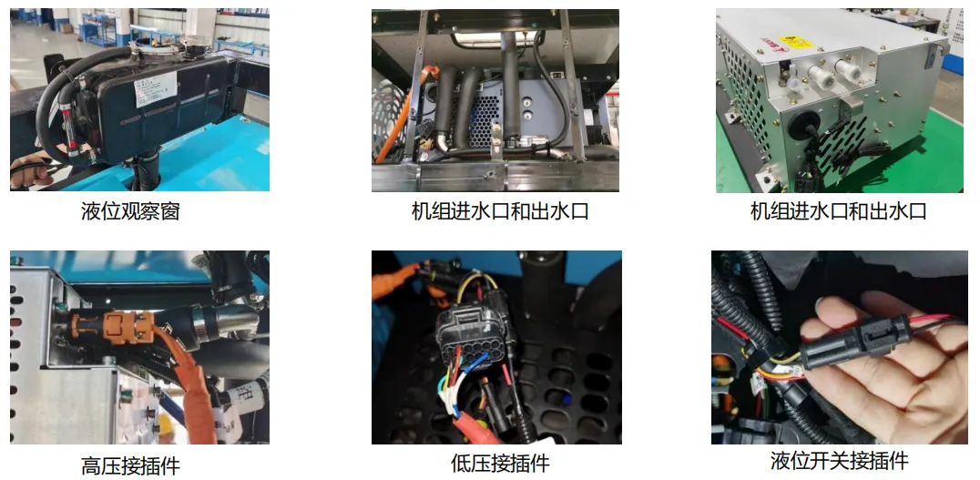
If there is any infringement, please contact the author to delete it.
The 282kwh charging version and battery replacement version battery box use 4 H-box batteries, and the liquid cooling circuit adopts a 2-parallel 2-series layout structure.
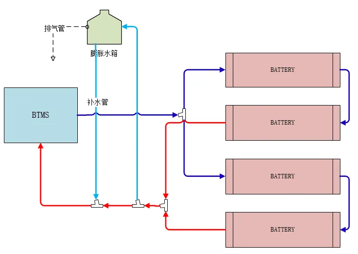
*System schematic diagram *Actual layout The 350kwh charging version and battery replacement version battery box use 10 C-box batteries, and the liquid cooling circuit adopts a 5-parallel 2-series layout structure.
*Physical Layout 0 2 Water-Chiller Introduction Structure and Principle Three Circuits (Liquid Cooling, Refrigerant, and Air)
The electronic water pump, plate heat exchanger, and battery liquid cooling channel constitute the liquid cooling circuit.
The compressor, condenser, expansion valve, and plate heat exchanger constitute the air conditioning circuit.
The electronic fan and condenser constitute the air conditioning circuit. Two Heat Exchange Locations: Plate heat exchanger: Heat exchange between the refrigerant circuit and the liquid cooling circuit.
Heat exchange between the refrigerant circuit and the air circuit of the air conditioning system. Structure and Key Components Introduction Three-in-One Controller: Consists of a PLC, DC-DC converter, and DC-AC controller. It collects data from high-pressure and low-pressure sensors, as well as inlet and outlet water temperature sensors, receiving operating instructions and target water temperatures from the BMS to control the operation of the electronic water pump, compressor speed, and electronic fan speed.
The component in the air conditioning circuit that absorbs, compresses, and discharges the refrigerant, completing the refrigerant circuit cycle. The compressor can only provide cooling capacity for the liquid cooling circuit when it is functioning properly.
This component drives the antifreeze circulation in the liquid cooling circuit. Only when the electronic water pump is functioning properly can it remove heat generated by the battery cells from the battery's liquid cooling plate, achieving battery cooling. The electronic fan: This provides a continuous flow of air to the condenser, forcibly dissipating the heat stored in the refrigerant into the air, dissipating the refrigerant's heat. The water cooling unit uses a suction fan, mounted outside the condenser. If the electronic fan malfunctions, a system pressure failure will occur.
This component converts high-temperature, high-pressure gaseous refrigerant into medium-temperature, high-pressure liquid refrigerant. If the refrigerant is clogged, the amount of air passing through the condenser will decrease, reducing the amount of heat removed from the condenser and the cooling capacity. This can result in a small temperature difference between the inlet and outlet water, causing the battery cell temperature to continue to rise. In severe cases, a system pressure failure may occur. Therefore, regular cleaning and maintenance of the condenser is required for all vehicles on the market.
A component that exchanges heat between low-temperature refrigerant and high-temperature antifreeze. The antifreeze temperature drops after passing through the heat exchanger; a temperature difference of 2°C-5°C is generally normal.
Expansion valve + temperature sensing bulb:
A component that converts medium-temperature, high-pressure liquid refrigerant into low-temperature, low-pressure liquid refrigerant. Its primary function is to sense the temperature within the compression-cooling pipe, control the opening of the expansion valve flow channel, and thereby control the refrigerant flow rate. The expansion valve and temperature sensing bulb are extremely sensitive to temperature fluctuations and are therefore protected by an outer insulation layer.
Low-pressure and high-pressure sensors collect pressure signals from the refrigerant circuit, while inlet and outlet water temperature sensors collect water temperature signals at the inlet and outlet of the water-cooling unit. The PLC controller uses these sensor signals to control the operation and speed of the compressor, electronic water pump, and electronic fan. Control method: Fault code: The TMS has three fault levels: Level 1 is the highest, Level 2 is medium, and Level 3 is the lowest.
(corresponding to Level 3 fault level for the entire vehicle) The BTMS is shut down. The unit is not operating and requires maintenance.
(corresponding to Level 2 fault level for the entire vehicle) The BTMS is in standby mode and may automatically recover after power is restored. After recovery, normal operation can be resumed.
(corresponding to Level 1 fault level for the entire vehicle) The BTMS is operating normally.